Reprogramming the H801 RGBW WiFi LED Controller for RGBW
The H801 is a 5 channel LED Controller. You can either control it with an Android App (the seller provides the .apk) or you try your luck and program it yourself - because it is based on a ESP8266!
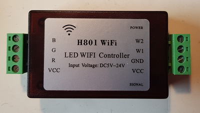
The H801 Board
The H801 offers 5 PWM outputs - for a RGBWW strip and two status LEDs - one green - one red.
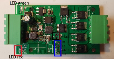
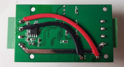
The PWM Mosfets seems to be 20N06L - 20 A, 60 V, N−Channel. There seems to be a NC245 between the ESP8266 pins and the MOSFETs - therefore the pins are active HIGH.
The Controller takes 5 - 24V.
Be careful with the sockets: both are 4 pins and would fit vice versa. So double check before you connect power to the dimmer!
The dimensions of the enclosure are 72 * 45 * 20 mm.
The OEM Android App for the H801
There's not so much to write about the OEM Android App. If you like the screenshots from the vendor download the APK and give it a try.If you don't bother - flash your own software.
Program the H801 with your own Software
There are several resources available in the internet, so I will only give a short summary.
You can program the ESP8266 with the Arduino IDE as "Generic ESP8266 Module". I recommend to disconnect any external power and to supply the ESP8266 from your USB-TTL interface. Currently I'm using a CP2101 interface. Shorten the flash jumper and start the upload. If the upload has finished, remove the jumper and do a power cycle of the device (there is no reset button on the board). I tried flash Size "1MB (FS256KB OTA: ~378KB)" to keep me an option for some more extensive HTML/JS/CSS data in the filesystem. These are my settings in the Arduino IDE:
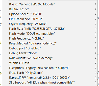
If you get OTA upload error messages like its an indicator that you have chosen the wrong flash size.
Uploading...............................................................

11:55:30 [ERROR]: ERROR[9]:
11:55:30 [ERROR]: ERROR[9]:
The usable pins/ports a defined as following:
const byte pwmRedPin = 15;   // GPIO15 red
const byte pwmGreenPin = 13; // GPIO13 green
const byte pwmBluePin = 12;  // GPIO12 blue
const byte pwmW1Pin = 14;    // GPIO14 white warm
const byte pwmW2Pin = 4;     // GPIO04 white cold
const byte ledGreenPin = 1;  // GPIO01 the green SMD LED on the PCB (left top corner) - TX Serial
const byte ledRedPin = 5;    // GPIO05 the red SMD LED on the PCB (left bottom corner)
const byte flashPin = 0;     // GPIO00 flash jumper
// RX Serial = 03            // on header available - can be used for sketch upload
// TX Serial1 = 02           // on header available - but Serial1 (!)
The PWM pins are obvious - they give you the PWM outputs via MOSFETs (active HIGH).
Additionally there are two SMD LEDs on the PCB which are connected to separate pins. These LEDs are LOW active.
After your first flashing the header for the flash pin could be used for a button. But keep in mind, not to press the button during start up - otherwise the ESP8266 will go into flash mode.
The RX of Serial on the header is available at the header, therefore you will use it to flash the device.
The TX of Serial1 needs some attention: It is available on a header, but it is Serial1. So if you need debug messages in your program, you have to send them to Serial1. In contrast, if you print to the default Serial - you will see that the green LED on the PCB will blink - the green LED is connected to GPIO01!
An Example Sketch for the H801 Dimmer
In the links you will find the download to a generic example sketch for the H801 dimmer. It implements an ESP8266 webserver and you can control the LEDs with your browser.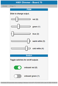
The webserver follows the ESP8266 examples webserver / HelloServer and consists of several parts:
These parts are the same for all my ESP8266 webservers, and if you read other tutorials on my page, you will already know this structure.
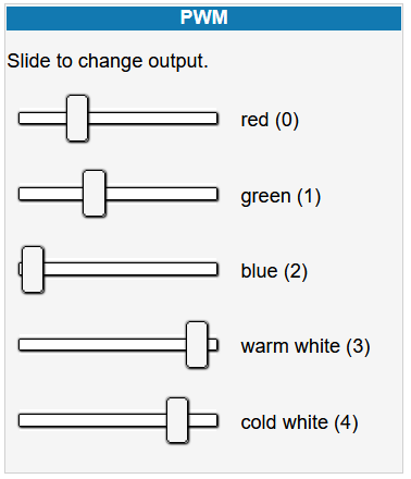
The dimmable LEDs use sliders. Technically they are input fields of type "range" and fire an event "oninput" - this means they will fire during the movement. You can try "onchange" also, if you only want to fire once when you have finished the setting.
The two LEDs are controlled with inputs of type "checkbox", but they are styled as rocket switches via CSS. They fire on click.
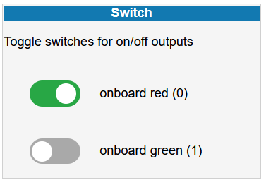
This means for both entries you will need activated JavaScript to make these elements working.
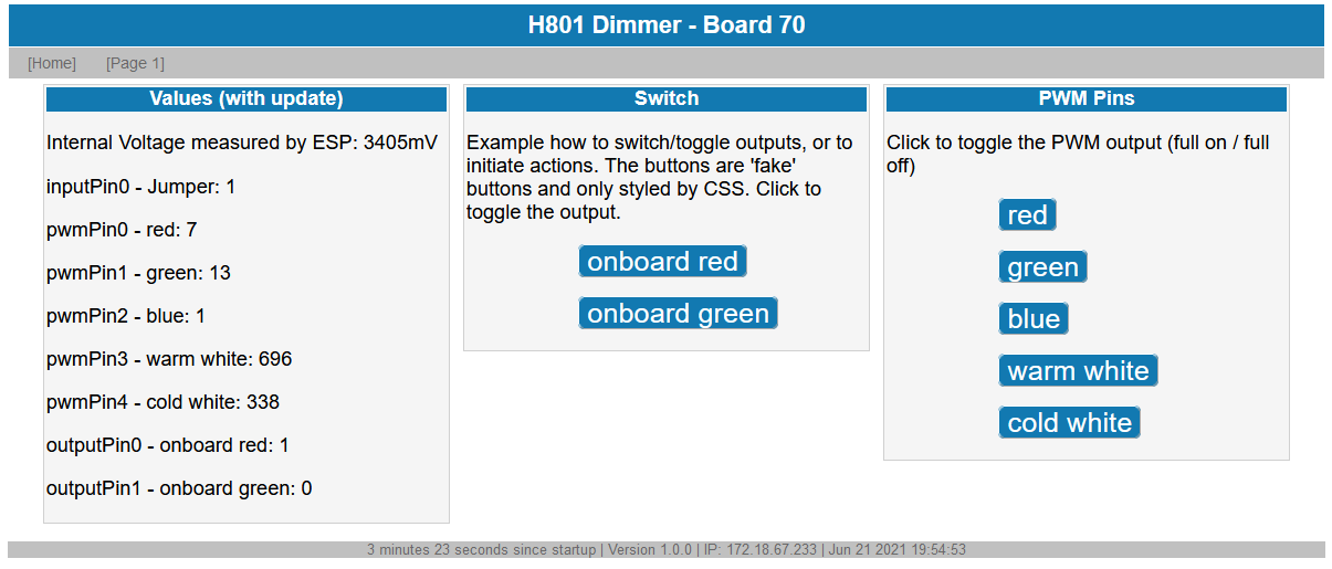
In the menu bar you can switch to page 1.htm. Page 1.htm contains all pin states and simplified buttons to control the outputs.
Before the upload you must set the #define USE_BOARD 79 and your wifi settings in the maintab.
If you want to read more about the generic ESP webserver sketch - see this page: Simple ESP8266 webserver.
Summary H801
The H801 is sold for about 10 - 15 USD. It's a bargain! A maker can't build it cheaper including an enclosure and the two plugs/sockets. The H801 WIFI Controller gives you a quick start for your RGB LED strips.