The ESP8266 ESP12F Relay X8 Board
This 8 channel relay board is equipped with an ESP8266 12F. It can be programmed with an USB-TTL adapter with the Arduino IDE.
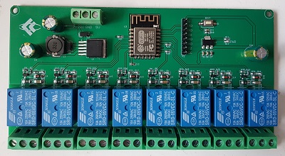
The Board
The microcontroller is an ESP8266 12F and can be programmed with the Arduino IDE. I use the settings of the NodeMCU 0.9 for the upload.
8 relays are connected to GPIOs. The outputs are HIGH active. The relays are connected to GPIO16, GPIO14, GPIO12, GPIO13, GPIO15, GPIO0, GPIO4 and GPIO5. On startup GPIO16 and GPIO15 will be active for a very short time - you will hear the two relays. Take this in consideration when you use these two relays as outputs.
GPIO0 and GPIO2 are available on a separate header, but remember, that GPIO2 is also connected to the (blue) LED on the ESP itself. The ADC is also available on the header. You can solder a header to gain access to following pins:
- 5V
- TXd - GPIO1
- RXd - GPIO3
- IO0 - GPIO0 - connect to GND and reboot (power cycle) if you need to set the ESP8266 in flash mode
- GND
- GND
- IO2 - GPIO2 - also used for the (blue) LED on the ESP8266
- ADC - A0 - the analog input of the ESP8266
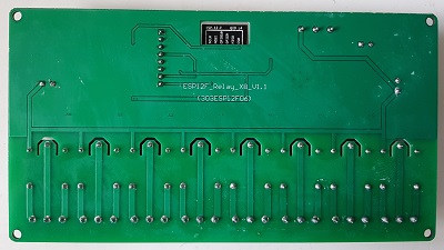
The 6 pins of the ESP8266 12F lower side are not connected to the PCB. If you need to use these IOs (11, 7, 9, 10, 8, 6), you have to solder them directly to the ESP.
The board can be supplied with DC 5V or DC7-28V. A step down converter LM2596S regulates the voltage to 5 V, and a smaller one is used to generate the 3.3V for the ESP8266. When all 8 relays are active, the board draws around 700mA @ 9.6V.
The board has cutouts between the relay pins, nevertheless don't use these
relays with mains electrics/230V
The dimension of the board is 148 * 79.8 * 19mm.
The Standard Software of the Relay Board
My relay board came with a test sketch. It activates all 8 relays in a sequence (like a KITT/Larson scanner) and opened a WiFi access point without password. You can connect a device to this WiFi , but I was not able to open a web server. I haven't found any information on how to use this WiFi (TCP? UDP?) therefore I wrote my own web server sketch.
How to program the Relay Board
The board can be programmed when you connect a USB-TTL to the respective header pins. RX/TX/GND and 5V are available on the header. To bring the ESP in flash mode connect IO0 to GND, press reset on the board and start the upload with the Arduino IDE. After the upload has finished, disconnect IO0 from GND and reset the board.
A simple Demo Sketch
I have put together a generic demo sketch. It is a simple ESP8266 webserver to switch the relays on or off. You can download this sketch at the end of this page.
The sketch offers several hardware variants / pin mappings and you must set the respective board in the main tab. The predefined pin mapping for this relay board is 71
#define USE_BOARD 71 // the ESP8266 8 channel board
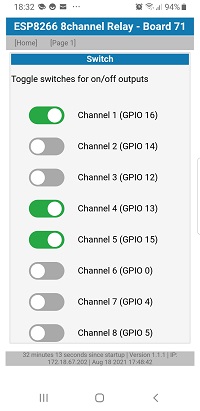
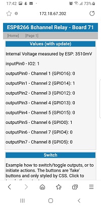
Page 1.htm is just for debugging. It shows the states of all pins and offers simple toggle buttons to switch the relays.
Exkurs: The Generic Demo Sketch
In general the generic sketch uses arrays of pin definitions. This makes maintenance for different boards very easy.
Before the first compile, go to the main tab and define which board variant you are using.
For this relay board use:
#define USE_BOARD 71 // the ESP8266 8 channel board
If you want to modify the configuration open tab config71.h
First you set a board name, this will be printed to serial and on the web GUI:
#if USE_BOARD == 71
#define TXT_BOARDNAME "ESP8266 8channel Relay"
All debug debug messages are printed to an interface called "Terminal". This board uses TX0, so just define a reference to Serial:
HardwareSerial &Terminal = Serial;
Then you declare all the pins:
const byte relay1Pin = 16;   // GPIO16 *
const byte relay2Pin = 14;   // GPIO14
const byte relay3Pin = 12;   // GPIO12
const byte relay4Pin = 13;   // GPIO13
const byte relay5Pin = 15;   // GPIO15 *
const byte relay6Pin = 0;    // GPIO0
const byte relay7Pin = 4;    // GPIO4
const byte relay8Pin = 5;    // GPIO5
//const byte io0Pin = 0;     // GPIO00 - flash Jumper - also used for relay6
const byte io2Pin = 2;       // GPIO02 - on header available
//const byte adcPin = A0;    // A0 - on header available
const uint8_t ledEspPin = 2; // GPIO02 is the (blue) LED on the ESP-12F
// RX Serial = 3             // on header available - can be used for sketch upload
// TX Serial = 1             // on header available
Now you can assign these pins to the arrays. Start with the input pin, currently I'm using only the free IO2 on the header:
Pin inputPin[] {
// the pin a name for the website
  {io2Pin, "IO2"}
};
Then assign pins to the 8 relays. The prompter will be printed in the web GUI and you must define if the relay is HIGH active (or LOW active). On this board all relays are HIGH active:
OutputPin outputPin[] {
// the pin a name LOW active (or high active)
  {relay1Pin, "Channel 1", HIGH},
  {relay2Pin, "Channel 2", HIGH},
  {relay3Pin, "Channel 3", HIGH},
  {relay4Pin, "Channel 4", HIGH},
  {relay5Pin, "Channel 5", HIGH},
  {relay6Pin, "Channel 6", HIGH},
  {relay7Pin, "Channel 7", HIGH},
  {relay8Pin, "Channel 8", HIGH}
};
This board doesn't have MOSFETs for PWM outputs, so instead of an array set following precompiler #define:
#define NO_PWMPIN
Finally, you can use the blue LED on the ESP8266 to indicate WiFi activity. If you need the LED for something different, set the variable to 255.
const byte wifiActivityPin = ledEspPin; // use ledEspPin or set to 255
#endif
This concludes the configuration of the ESP8266 8 channel relay board.
Don't forget to either set your WiFi credentials or include your settings in the main tab.
This generic webserver sketch is compatible for ESP8266 and the ESP32, hence the precompiler defines to differentiate the boards based on your upload settings. If you want to read more about the generic ESP webserver sketch - see this page: Simple ESP webserver.
Pricing of the ESP8266 X8 Relay Board
This 8 channel relay board is available for less than 20 EUR including shipping and VAT. It might not be a super cheap offer, but if you just need a relay board with an ESP8266, a DC/DC converter and don't want to wire three separate boards - take it!
Summary on the ESP8266 8 channel relay Board

This 8 channel relay board is a compact solution if you just need 8 simple relays driven by an ESP8266.